Winch & Hoist Engineering

American Crane & Hoist manufactures both electric and air powered industrial winches. ACH industrial winches are built to provide reliability and assurance in handling the movement of industrial scale products and materials. ACH industrial winches are designed and constructed to provide the user with the best power and durability for a company’s lifting and pulling operations.

ACH industrial winches can have free spooling drums. They can be built with a torque limiter mechanical clutch that is automatically reset when excessive pull is released. In addition, there can be an automatic holding drum brake and electric shutoff. ACH industrial winches can have a cable drum pressure roller that assists in multiple layer reeving, keeps the wires taut on the drum when free spooling or when slack line occurs. Our industrial Car Pullers have two wire ropes that wind and unwind evenly to allow pulling in 2 directions without having to reattach the wire ropes. For very long line pulls our ERP continuous car puller can pull an unlimited amount of wire rope.

ACH winches used in industrial applications and settings have a totally enclosed motor which is part of the ACH high torque crane and hoist duty motor with a starting capacity of a minimum two times running. The industrial winches have drum support bearings as part of ACH heavy duty roller bearing assemblies. Industrial winches have an all steel fabricated winch base and drum for maximum durability with minimum 5 to 1 structural safety factor.

Technical Information

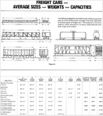
Car pullers are rated and sold on the basis ot their pulling capacity in pounds at the drum, not on the number of cars they can pull.

Proper selection of a car puller for any particular application should be made on the basis of existing conditions and the requirements which must be satisfied.

The rope pull required is dependent upon several variables, weight and condition of cars to be handled, the grade, any track curvature or switches and the condition of track, and ambient temperature. A greater pull is required to start the cars than to keep them moving after being started. Normally the estimated rope pull required is that neces-sary to move the cars after they have been started, it is assumed that the starting capacity of the electric car puller is a minimum two(2) times the running capacity and sufficient to start the cars moving.

The following information has been tabulated to help determine the required rope pull of a car puller to suit the application and various conditions that exist. (Stanspec Corporation Engineering will be happy to size a system to suit your application upon request, providing accurate pertinent data of conditions and requirements are furnished.)

Required (Running) Rope Pull =W1(A + B + C) + W2(D) + W3(E)
Where: W1 = Maximum gross weight of cars
and contents (tons)
W2 = Maximum gross weight of cars and
contents within curved section of track (tons)
W3 = Maximum gross weight of cars
and contents within switches (tons)
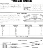
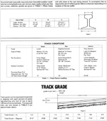
A = Track Factor Loading (///Ton): Table 1
B = Grade Factor Loading (///Ton): Table 2
C = Temperature Factor Loading (///Ton): Table 3
D = Curve Factor Loading (///Ton): Table 4
E = Switch Track Factor Loading (///Ton): Table 5

Example:Criteria Given:
A car puller is required to move ten (10) loaded cars, each
having a live load of 35 tons with each car weighing 54,000 Lbs.
It will be necessary to pull through a 3° curve. A switch track
of 12° is present to pull onto siding. Track condition is fair, rail
is 115#. Lowest ambient temperature at location will be 20°F.
Entire track is on approximately 1% grade.

SOLUTION :
Rope Pull Required = W1(A + B + C) + W2(D) + W3(E)
Step I: Total weight of car =
35ton + 54000# = 62 tons
2000#
W1 =(10)(62) = 620
From Table One(1): Line pull per ton on a Fair track
condition
A = 15 Lbs.

Step II: From Table Two(2): Line pull per ton for a 1% grade
B = 20 Lbs.

Step III: From Table Three (3): Line pull per ton required for
operation in 20°F area
C = 3 Lbs.

Step IV: Assume car length to be approximately 50′-0″.
A 3° curve has a radius of curve of 1910 feet(from Table 4)
Circumference of
curve = (19l0x2)(3.1416)*3 = 100.00 Feet360Number of
cars in curve= Circum. of Curve = 100′ = 2Length of Car         50′
W2 =(2)(62 Tons)= 124 Tons
From Table 4: Line pull per ton for a 3° curve. D = 4 Lbs.

Step V: Approximate length ot curve in switch is 67 feet.
(From Table 6—12°curve — lead = 67 feet)
Number of
cars in curve = Lead = 67 = 1.34
Length of Car 50
W3 = Number of cars in curve x total weight of car.
=1.34 x 62 Tons= 83 08 Tons
From Table 5: Track curvature in switch is 12° —
per Note Figure 4: Add 2 Lbs. per
degree of curvature
E = 12° x 2 Lbs. = 24 Lbs.

Final Calculation
W1 = 620 tons(Slep I)
A = 15 Lbs.
B = 20 Lbs.(Step II)
C = 3 Lbs.(Slep III)
W2 = 124 tons(Slep IV)
D = 4 Lbs.
W3 = 83.08 tons(Step V)
E = 24 Lbs.

Formula:
Line Pull = W1(A + B + C) + W2(D) + W3(E)
= 620(15 + 20 + 3) + 124(4) + 83.08(24)
= 23560 + 496 + 1994 ±
= 26050 Lbs. of running line pull requited.

Rope Strength and Fleet Angle

Rope Strength and Fleet Angle

DEFINITION:

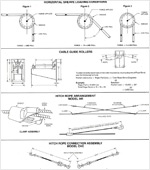
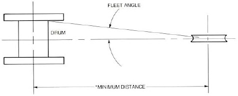
FLEET ANGLE: The angle of the tope from a fixed sheave or connection point to the drum flange. This condition should not exceed 3° for a grooved drum or 11/2’0 for an ungrooved drum.

* A general rule of thumb for determining the nearest sheave or pin connection is based upon drum length as follows:

For every 12″ of drum length center distance is: 20’0″ tor ungrooved drum. 10’0″ for grooved drum.

Sheave should be centered on drum lenglh as shown in illustration.

In Ihe even! Ihis criteria cannot be met contact the factory for engineered application requirement to suit your particular application.


Typical Track Layouts

ONE-WAY CAR TRAVEL
ONE-WAY CAR TRAVEL
This type of drive incorporates a single direction carpuller with direct wire rope connection lo car lorone-way travel.
TWO-WAY CAR TRAVEL
TWO-WAY CAR TRAVEL
This drive incorporates a single direction car pullerutilizing one fleet sheave and one drop side sheaveto accomplish two-way car travel.
One-Way Car Travel
ONE-WAY CAR TRAVEL
This drive is direct wire rope connection with a single direction car puller and one fleet sheave (or one-way car travel.
Reversing Direction Car Travel
REVERSING DIRECTION CAR TRAVEL
This application best suits short distance fixed car travel and consists of a dual direction car puller, centered sheaves with positive control for reversing and spotting two-way car travel.
Reversing Direction Car Travel
REVERSING DIRECTION CAR TRAVEL
For an application requiring long distance car travel, a dual direction continuous car puller with by-pass sheave orientation to achieve reversing and precision spotting two-way car travel.
Reversing Direction Car Travel
REVERSING DIRECTION CAR TRAVEL
A pil locaied dual direction car puller either continuous or fixed travel can be used to achieve application requirements and precision spotting with braking. Minimize above surface drive area requirements
Two-Way Two-Track Car Puller
TWO-WAY TWO-TRACK CAR PULLER
A continuous puller in a closed loop system is used to accomplish two direction movement of cars on either track for controlled spotting and braking. The car puller can be positioned to suit the application requirements.
Curved Track Two-Way Car Puller
CURVED TRACK TWO-WAY CAR PULLER
This arrangement can be accomplished using either a single direction car puller with drop sheaves for two direction movement, or a continuous car puller in a closed loop arrangement.

back to top